Wheatstone bridge can be used to determine the value of an unknown resistance in the arrangement of four resistances among which three are known resistances. It was invented by British physicist Charles Wheatstone in 1843.
The arrangement for Wheatstone’s bridge is shown in the figure.
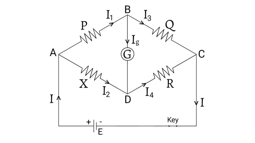
The Wheatstone bridge consists of three known resistances $P$, $Q$ and $R$ and a fourth known resistance $X$. A source of emf $E$ is connected between two points $A$ and $C$ and a galvanometer between $B$ and $D$. The resistance of galvanometer is $G$. This circuit is a bridge because the galvanometer is bridged across two parallel branches $ABC$ and $ADC$. Let $I_1$, $I_2$, $I_3$, $I_4$ and $I_g$ are the currents in the resistances $P$, $X$, $Q$, $R$ and $G$ respectively.
Balanced Condition in Wheatstone Bridge
Applying Kirchhoff’s current law at points B and D, we get, \[I_1=I_3+I_g \;\; \text{__(1)}\] \[I_2+I_g=I_4\] \[I_2=I_4-I_g \;\; \text{__(2)}\]
Applying Kirchhoff’s voltage law in the loop ABDA, we can write \[I_1P+I_gG-I_2X=0\]
$\because$ There is no cell in this mesh so $E=0$.
\[I_1P=I_2X-I_gG \;\; \text{__(3)}\] Applying Kirchhoff’s voltage law in the closed circuit $ABCDA$, we can write \[I_1P+I_3Q-I_2X-I_4R=0\] \[I_1P+I_3Q=I_2X+I_4G \;\; \text{__(4)}\]
Bridge circuit is balanced when the potential difference between $B$ and $D$ will be zero so no current passes through the galvanometer i.e. $I_g=0$ and hence, the galvanometer shows null deflection.
Therefore, from equation $(1)$, $(2)$ and $(3)$, \[I_1=I_3 \;\; \text{__(5)}\] \[I_2=I_4 \;\; \text{__(6)}\] \[I_1P=I_2X \;\; \text{__(7)}\] Therefore, from equation $(4)$, $(5)$ and $(6)$, \[I_1P+I_1Q=I_2X+I_2R\] \[I_1(P+Q)=I_2(X+R)\;\;\text{__(8)}\] Dividing equation $(8)$ by $(7)$, \[\frac{I_1(P+Q)}{I_1P}=\frac{I_2(X+R)}{I_2X}\] \[1+\frac{Q}{P}=1+\frac{R}{X}\] \[\frac{Q}{P}=\frac{R}{X}\] \[\frac{P}{Q}=\frac{X}{R}\]
This is the balanced condition for the Wheatstone bridge. The bridge is most sensitive when all the four resistances are of the same order. It is not suitable for the measurement of very low and very high resistance.
Meter Bridge (Slide Wire Bridge)
Meter Bridge is the simplest form of Wheatstone bridge. It consists of a resistive wire of uniform thickness so that its resistance per unit length remains constant. The resistive wire should be of high resistivity and low value of temperature coefficient such as the wires of mangnin, constantan etc. so that the resistance is not affected due to the change in temperature.
The length of wire is often a meter so the device is named as meter bridge. The balanced condition is obtained by adjusting the length by sliding jockey so this device is also named as Slide Wire Bridge. The length of wire is not necessarily to be of $1$ meter but varies from $0.5$ meters to $1$ meter or more according to requirement.
Construction: The stretched wire $AC$ is fitted between two fixed terminals made in a wooden board having a parallel measuring scale. Thick copper strips having negligible resistance are fitted on the wooden board having the gaps. The strips join the fixed terminals on the board. The knob of central strip is connected to a galvanometer $G$ with a jockey $J$.
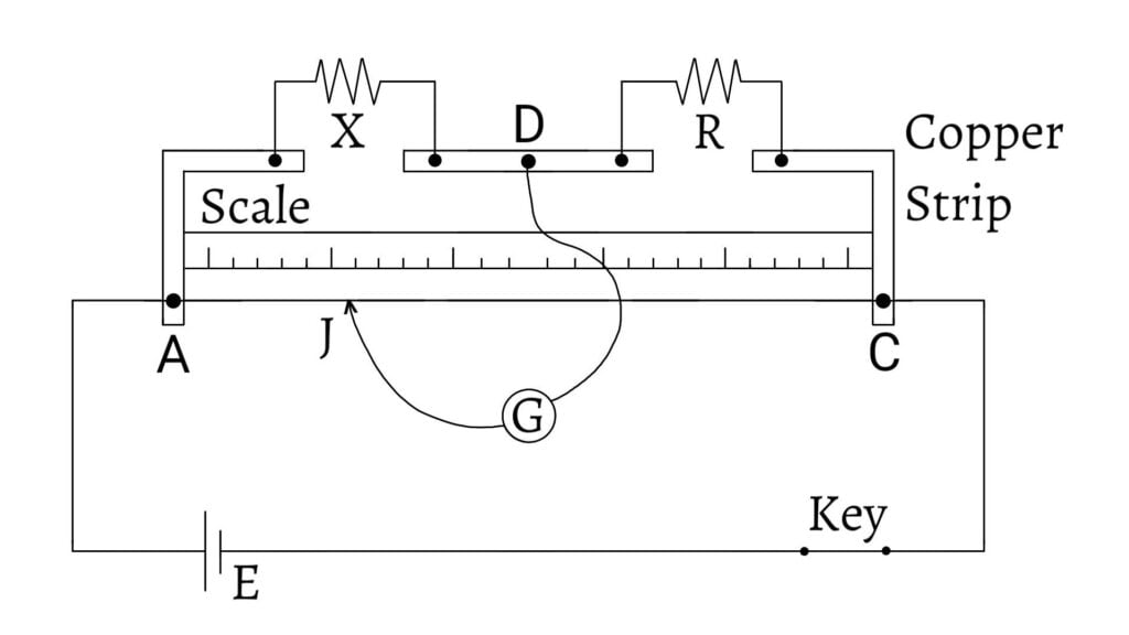
Principle: It works on the principle of Wheatstone’s Bridge i.e. \[\frac{P}{Q}=\frac{X}{R}\;\;\text{__(1)}\]
Since the bridge wire is of uniform cross section, resistance of the wire length of the wire. \[\therefore\frac{P}{Q}=\frac{\text{Resistance of AJ}}{\text{Resistance of CJ}}=\frac{X}{R}\]
Let the total length of wire $AC = 100$ cm. If $AJ = l$ cm, then $CJ = (100-l)$ cm. \[\therefore \frac{P}{Q} = \frac{l}{100-l}\;\;\text{__(2)}\]
From equations $(1)$ and $(2)$, we have, \[\frac{l}{100-l}=\frac{X}{R}\] \[\therefore X=\frac{l}{100-l}×R\]
Hence, by knowing the values of $l$ and $R$, we can determine the unknown resistance$X$.
Previous: Kirchhoff’s Circuit Laws
Next: Potentiometer