AC Through Inductor and Resistor in Series (LR Circuit)
Let an inductor of inductance $L$ and a resistor of resistance $R$ be connected in series to an ac source of emf $E$ and frequency $f$ as shown in the figure given below. This type of circuit is known as LR circuit.

The potential difference across inductor \[V_L=IX_L\] In the inductor, voltage $V_L$ leads current $I$ by a phase angle of $\frac{π}{2}$. [From: AC Through an Inductor (AC Through Circuit Elements)]
The potential difference across resistor \[V_R=IR\] In the resistor, voltage $V_R$ and current $I$ are in same phase. [From: AC Through a Resistor (AC Through Circuit Elements)]

Since $V_R$ and $I$ are in same phase, $V_R$ is represented by $OA$ in the direction of $I$. $V_L$ is represented by $OB$ perpendicular to the direction of $I$ because $V_L$ leads $I$ by a phase angle of $\frac{π}{2}$. As the resultant of $V_L$ and $V_R$ is equal to $E$, by using Pythagoras theorem in $\Delta OAC$, \[OC=\sqrt{OA^2+OB^2}\] \[\therefore E=\sqrt{V_R^2+V_L^2}\]
\[E=\sqrt{I^2R^2+I^2X_L^2}\] \[E=I\sqrt{R^2+X_L^2}\]
Hence, the current in the circuit is given by \[I=\frac{E}{\sqrt{R^2+X_L^2}}\]
Also, if $Z$ be the impedance of the circuit, then \[Z=\frac{E}{I}=\sqrt{R^2+X_L^2}\]
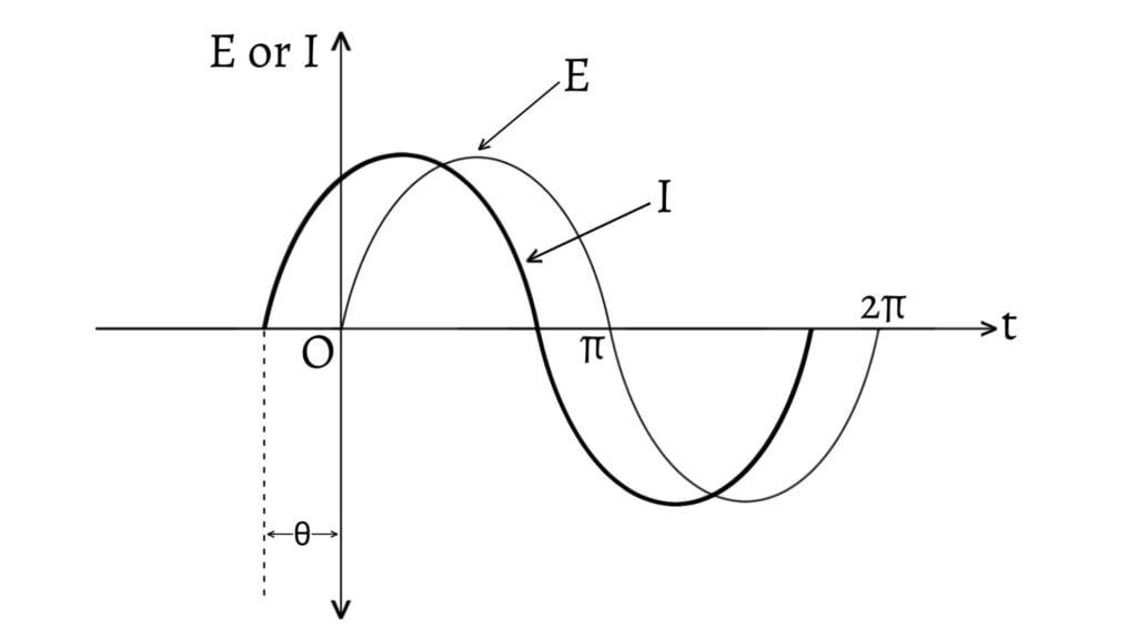
If the voltage $E$ leads the current $I$ by an angle $\theta$, then \[\tan\theta=\frac{AC}{OA}=\frac{V_L}{V_R}=\frac{X_L}{R}\] \[\therefore\theta=\tan^{-1}\left(\frac{X_L}{R}\right)\]
The phase relation between current and voltage in LR circuit is graphically shown below.

AC Through Capacitor and Resistor in Series (CR Circuit)
Let a capacitor of capacitance $C$ and a resistor of resistance $R$ be connected in series to an ac source of emf $E$ and frequency $f$ as shown in the figure given below. This type of circuit is known as CR circuit.

The potential difference across capacitor \[V_C=IX_C\] In the capacitor, voltage $V_C$ lags behind current $I$ by a phase angle of $\frac{π}{2}$. [From: AC Through a Capacitor (AC Through Circuit Elements)]
The potential difference across resistor \[V_R=IR\] In the resistor, voltage $V_R$ and current $I$ are in same phase. [From: AC Through a Resistor (AC Through Circuit Elements)]

Since $V_R$ and $I$ are in same phase, $V_R$ is represented by $OA$ in the direction of $I$. $V_C$ is represented by $OB$ perpendicular to the direction of $I$ because $V_C$ lags behind $I$ by a phase angle of $\frac{π}{2}$. As the resultant of $V_C$ and $V_R$ is equal to $E$, by using Pythagoras theorem in $\Delta OAC$, \[OC=\sqrt{OA^2+OB^2}\] \[\therefore E=\sqrt{V_R^2+V_C^2}\]
\[E=\sqrt{I^2R^2+I^2X_C^2}\] \[E=I\sqrt{R^2+X_C^2}\]
Hence, the current in the circuit is given by \[I=\frac{E}{\sqrt{R^2+X_C^2}}\]
Also, if $Z$ be the impedance of the circuit, then \[Z=\frac{E}{I}=\sqrt{R^2+X_C^2}\]
If the voltage $E$ lags behind the current $I$ by an angle $\theta$, then \[\tan\theta=\frac{AC}{OA}=\frac{V_C}{V_R}=\frac{X_C}{R}\] \[\therefore\theta=\tan^{-1}\left(\frac{X_C}{R}\right)\]
The phase relation between current and voltage in CR circuit is graphically shown below.
Previous: AC Through Circuit Elements
Next: LCR Circuit