Let an inductor of inductance $L$, a capacitor of capacitance $C$ and a resistor of resistance $R$ be connected in series to an ac source of emf $E$ and frequency $f$. Such circuit is known as LCR circuit.

The potential difference across the inductor is \[V_L=IX_L\] In the inductor, voltage $V_L$ leads current $I$ by a phase angle of $\frac{π}{2}$. [From: AC Through an Inductor (AC Through Circuit Elements)]
The potential difference across the capacitor is \[V_C=IX_C\] In the capacitor, voltage $V_C$ lags behind current $I$ by a phase angle of $\frac{π}{2}$. [From: AC Through a Capacitor (AC Through Circuit Elements)]
The potential difference across the resistor is [V_R=IR] In the resistor, voltage $V_R$ and current $I$ are in same phase. [From: AC Through a Resistor (AC Through Circuit Elements)]

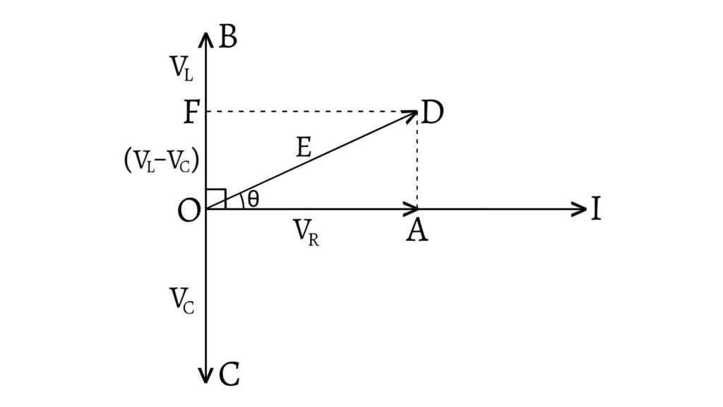
Since $V_R$ and $I$ are in phase, so $V_R$ is represented by $OA$ in the direction of $I$. $V_L$ leads $I$ by and angle of $\frac{π}{2}$ so $V_L$ is represented by $OB$ in the direction perpendicular to $I$. Similarly, $V_C$ is represented by $OC$ in the direction perpendicular to $I$ because $V_C$ lags behind $I$ by an angle of $\frac{π}{2}$.
If $V_L>V_C$, then $(V_L-V_C)$ is the resultant of $V_L$ and $V_C$ as they are in opposite directions. The resultant of $V_R$ and $(V_L-V_C)$ is represented by $OD=E$. Now, by using Pythagoras theorem in $\Delta OAD$, \[OD=\sqrt{OA^2+AD^2}\] \[\therefore E=\sqrt{V_R^2+(V_L-V_C)^2}\] \[E=\sqrt{I^2R^2+(IX_L-IX_C)^2}\] \[E=I\sqrt{R^2+(X_L-X_C)^2}\text{ __(1)}\]
Hence, the current in the circuit is given by \[I=\frac{E}{\sqrt{R^2+(X_L-X_C)^2}}\text{ __(2)}\] Also, \[\frac{E}{I}=\sqrt{R^2+(X_L-X_C)^2}=Z\text{ __(3)}\] where, $\frac{E}{I}=Z$ is the effective opposition of LCR circuit to ac current which is called impedance of the circuit.
If $\theta$ be the phase angle between $E$ and $I$, then \[\tan\theta=\frac{AD}{OA}=\frac{V_L-V_C}{V_R}=\frac{X_L-X_C}{R}\] \[\therefore\theta=\tan^{-1}\left(\frac{X_L-X_C}{R}\right)\text{ __(4)}\] \[\text{or, }\theta=\tan^{-1}\left(\frac{\omega L-\frac{1}{\omega C}}{R}\right)\text{ __(5}\]
Special Cases for LCR Circuit
- When $X_L>X_C$ $(V_L>V_C)$, i.e. $X_L-X_C$ is positive, then $\tan\theta$ is positive. So $\theta$ is positive and hence voltage leads the current by a phase angle of $\theta$. In this case, the circuit is inductive.
- When $X_L<X_C$ $(V_L<V_C)$, i.e. $X_L-X_C$ is negative, then $\tan\theta$ is negative. So $\theta$ is negative and hence voltage lags the current by a phase angle of $\theta$. In this case, the circuit is capacitive.
- When $X_L=X_C$ $(V_L=V_C)$, i.e. $X_L-X_C$ is zero, then $\tan\theta$ is zero. So $\theta$ is zero and hence voltage and current are in same phase. This is the condition for electrical resonance in the circuit. From equation $\text{(3)}$, \[Z=\sqrt{R^2}=R\] Hence in this case, the circuit is purely resistive.
Previous: LR and CR Circuits
